


Component Video Cables -- A Guide
Component video cable, in just a few years, has gone from being a relatively uncommon and esoteric way to hook up video devices to being the near-universal analogue video signal standard for home theater and high-definition television. Where a few years ago s-video and composite were the most common and widely usable video signal standards, component video has emerged as the leader among analogue hookup methods because it is the only common consumer analogue signal type which supports progressive scan and high-definition resolutions, and because it is the standard output format of DVD players.
Component video cables, then, are needed in most home theater setups. Naturally, people want to know: what makes the best component video cable? Why are there so many component video cable types on the market? How can I choose the component video cable that will do the best job in my system? To help address these questions, we've put together this little treatise on component video, and component video cables.
What is Component Video?
Before we get to the subject of what a component video cable is, let's talk about what component video is. All conventional methods of sending an analogue video signal from one device to another involve a few basic types of information. These types are the scan information (e.g., when does a line of video start and end, and when does a frame start or end?), the brightness information (how bright should this part of the image be?) and the colour information (what colour should this part of the image be?). Composite video, s-video, component video, and the various types of RGB video all constitute different methods, or formats, for delivering this information. At one extreme is composite video; all of the information, from the sync pulses used to deliver scan information to the luminance (brightness) and chrominance (colour) portions of the signal are all delivered as one unified, "composite" signal, traveling down one wire. At another extreme is RGBHV; instead of one wire, there are five, carrying horizontal sync, vertical sync, and the brightness of each of the colour components, red, green, and blue.
Component video is akin to RGBHV, in that its colour information is broken out into pieces to keep red, green and blue separate. However, instead of delivering red, green and blue as such, component video is what is known as a "colour-difference" signal. To reduce the number of connections from five to three, the horizontal and vertical sync signals are combined with one of these signals, so that we have three connections. The "green" connection, rather than carrying green as such, is the Y, or "luminance," channel, and in addition to carrying a signal for the total brightness value, it carries the sync pulses. The "red" channel, Pr, instead of carrying the red value, carries a difference signal: R-Y, or red minus total luminance, usually referred to as "Pr." The "blue" channel, likewise, carries B-R, blue minus luminance, or "Pb." The display interprets the Y, Pb and Pr components of the signal and derives the values of red, green and blue from them. This, combined with the scan information, allows the display to render the intended picture.
Component video is a multiscan format, which is to say that it may be delivered, unlike composite or s-video, in however many lines and at whatever frame rate one wishes, in either interlaced or progressive scan modes. This is why, when you're hooking a DVD player up to a display, progressive scan mode is ordinarily only available through the component video output; and this is also why, when dealing with a device like an HD TiVo, one can only get the high-definition analogue output when using a component video cable connection.
What is Component Video Cable?
For many years, the standard method of hooking analogue video devices to one another has been through 75 ohm video coaxial cable. Long before these cables were in common use in the home, broadcast and production houses were wired with 75 ohm video cable, generally running composite video. The advantages of 75 ohm video coax include excellent impedance tolerance (good for preventing signal reflection, which causes ringing and ghosting), excellent shield performance (important in a high-noise environment like a TV studio), and low loss (good when one needs to run video over long distances without significant degradation). Not too surprisingly, when component and RGB video came into common use, the same type of cable was used to hook them up--the difference being, of course, that when there are three signals, as in a Y/Pb/Pr component video cable run, one needs three cables to run them in.
So, whether they're joined together in a sheath, bonded together in a ribbon configuration, or just run separately, component video cables always consist of three cables which are electrically separate. Each member of the set of three is its own, separate 75 ohm video coaxial cable, with its own center conductor and shield.
But what does it mean to say that a cable is "75 ohm," or "coaxial"? Well, a "coaxial" cable, or "coax," is simply a cable in which all of the elements share a common physical axis. What this means is that the elements of the cable are cylindrical (at least, when the cable is not bent), and are laid around one another, so that the axis around which the jacket, shield, and dielectric (the insulating layer between the center conductor and shield) are constructed is the same as the axis of the center conductor. If you cut a piece of coaxial cable, the cross-section looks like the drawing at right. | 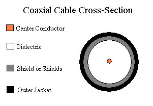 |
When we say that a video cable is "75 ohm" cable, this is a reference to the cable's "characteristic impedance." Characteristic impedance is a bit difficult to understand; although it's expressed in ohms, like resistance, if you take a volt-ohmmeter to a video cable, you won't find 75 ohms of resistance anywhere. Characteristic impedance has to do with whether the cable is electrically matched to the input and output circuits of video devices, which are all designed to accept or emit signals at 75 ohm impedance (meaning, essentially, that for every volt of signal presented, current will flow through the circuit at the rate of 1/75 ampere). When device inputs and outputs are not impedance-matched, portions of the signal can be reflected back and forth through the connection between them; in a severe case, this will manifest itself as ghosting, or "ringing," of the image. When a cable is badly-matched to the input and output impedances, the output device, in a manner of speaking, "sees" a load of the wrong impedance, and the input device does likewise, causing these reflections.
Component Video Cable Connectors
All good things, as they say, must come to an end, and that's true of video cables as well. Instead of terminating video cables directly into our television sets, projectors, DVD players, and the like, we use connectors to make those junctions. The quality of these connectors can be an issue with component video cables, and is worth a look.
First, it's important to point out that there is no such thing as a "component video connector." Component video can be run through any of a variety of connector types, and it's still component video. RCA, BNC and other connectors are commonly used, and these connector types can be used for other types of video as well, so it's a good idea not to mix connector types and signal types when speaking of component video cables. We're often asked whether, for example, we can make a component video cable that "goes from component to BNC," and the answer to that question depends on just what's meant. If the question is whether we can build a component video cable with BNC connectors on one end, the answer is yes; if the question is whether we can run component video into a BNC composite, RGBHV or Y/C connection, the answer is no (at least, not without a converter box of some sort).
The most common form of connector for component video cables is the RCA connector. This connector was, of course, named for the familiar RCA company, Radio Corporation of America, and is often referred to as a "phono" connector because its original application was to allow the audio output of a phonograph to be fed into a radio or other amplifier. RCA jacks (the "female" RCA connector) are familiar to anyone acquainted with consumer electronic equipment as the standard plug-in points for audio of all sorts and, nowadays, for most composite and component video; at right is a photo of a set of RCA jacks meant to accept a conventional component video cable. | 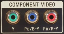 |
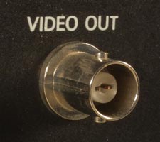 | Most professional gear, and some high-end consumer gear, uses another type of connector: the BNC, a bayonet-style connector. A BNC jack (see photo at left) looks quite different from an RCA jack--it sticks more prominently out of the equipment panel, has a smaller pin socket (which looks not unlike a pin itself, until one realizes that the "pin" is hollow), and has two nubs on the outside of its outer contact to accept the turning bayonet ring on the male connector. |
Component video is sometimes run through a VGA, or "HD15" type connector, which has fifteen pins, arranged in three rows of five; this is done most often on projectors, probably to save space, and is a source of potential confusion because the standard VGA signal format, which many projectors also accept, is not component video but RGBHV. One cannot always assume that a device with an HD15 input will accept component video; computer monitors almost never will, data projectors sometimes will, and home theater projectors almost always will. If component is accepted, the signals go in to pins 1 (Pr), 2 (Y), and 3 (Pb), with the grounds going to pins 6, 7 and 8, respectively; this, fortunately, corresponds to the pinout for red, green and blue in a conventional VGA/RGBHV signal, so we can use the same adapters and cables with component that we use with those signal types. The HD15 is a nasty little connector, not really well-adapted to this sort of use, and poorly sized from the point of view of video cable--but when you've got to use one, of course, none of that matters much.
Obviously, for each type of connector on an equipment panel, there's a corresponding male connector that plugs into it. The vast majority of consumer equipment uses RCA inputs and outputs, so the vast majority of component video cables are built with RCA plugs to go into those jacks. The RCA plug and jack, having been designed for analogue audio, were not designed to match a 75 ohm characteristic impedance, and their dimensions are such that they can't be matched to 75 ohms. What one can do, however, is make the length of the mismatch as short as possible, which minimizes the impact of the mismatch. Canare crimp RCA plugs do this by carrying the coaxial structure and dimensions of the cable forward into the plug body as far as possible; generally speaking, solder-type RCA plugs are inferior from an impedance match standpoint because the need to provide contact for soldering and allow space to screw on the connector shell do not allow the 75 ohm impedance to be carried as close to the tip as in the Canare design. There are a few other crimp plug designs on the market which are akin to Canare's--ADC, for example--but most manufacturers of component video cables use solder connections.
Apart from impedance match, the most important characteristics of an RCA plug for use in a component video cable are its mechanical stability--that is, how well it will hold up to usage--and its facility for making good electrical contact with equipment jacks. Plating with a non-corroding metal, such as gold or nickel, helps prevent oxidation from compromising the quality of the contact, and the ideal plug should grip the jack firmly without being so tight as to damage it. Here again, we're partial to the Canare plugs, which use a set of spring contacts to grip the jack but which can be removed easily enough with a firm tug; we have occasionally had customers report that the plugs on some of the common consumer cable brands are so tight that, when a cable was unplugged, the plug pulled the jack right off the back panel of the device. That certainly makes the point that sheer mechanical grip strength, without a mechanism that enables easy removal, isn't necessarily a good thing.
Component Video Cable Quality
So, what makes a high-quality component video cable? It really boils down to a few technical considerations; we'll go through those, and meanwhile touch on a few issues which don't really matter as much as is commonly believed.
Size is Overrated
Over normal run lengths and with cable of reasonable parameters, the amount of signal lost to resistance in the cable is not particularly significant; this is especially so because, even to the extent that resistance causes loss, the loss is linear--it affects all frequencies in the signal almost equally, and so when the display receives the signal and adjusts its amplitude (usually done by reference to the strength of the sync pulses), all of the information is still present regardless of the loss of signal strength. Over reasonable run lengths (say, under 100 feet), these losses are not really significant so long as one is dealing with a cable having a reasonably-sized center conductor (say, 22 AWG or larger).
So, What Really Matters?
But there are technical deficiencies a component video cable can have, which can have dramatic impact upon signal quality, especially where runs are sufficiently long to make the impedance of the cable a significant consideration. With full-blown HD component running at about 35 MHz (that's 1080i; 1080p/60 would be double that), the wavelength of the signal, corrected for the speed of propagation in a high-quality coaxial cable, is about 24 feet, making even a six-foot component video cable a significant fraction of the wavelength and potentially a factor in signal quality (and, in the case of 1080p/60, those distances are halved).
What's All This About Impedance?
Here, one might ask: isn't it sufficient to make sure that the video cable is 75 ohms? After all, that's the impedance required to match all common video gear, and if one uses 75 ohm cable, there's nothing else to think about where impedance is concerned...and that would be true, if we lived in a perfect world where cables always met their design objectives perfectly. In practice, cable is seldom exactly 75 ohms. Small variations in the shape and diameter of the wire used in the center conductor, the consistency of the dielectric, the centering of the wire within the dielectric, the size and tightness of the shield around the dielectric, and the behavior of the cable when flexed, make it impossible to build cable precisely and always at 75 ohms. For that reason, any manufacturer of video cable is always working to produce cable within an acceptable range around 75 ohms. A manufacturer specifies how close the cable is guaranteed to be to 75 ohms in a spec called "impedance tolerance," expressed as a +/- range. Without a published specification for impedance tolerance, there's no way to know whether that "75 ohm" cable is 75 ohms plus or minus 1.5 ohms, or 5 ohms, or 15 ohms. This tolerance is the single most important technical spec to look to in determining video cable quality, especially at long lengths; the best video cables available today, "precision" video cables designed for serial digital video transmission, control impedance to a published spec of +/- 1.5 ohms, and, as a practical matter, rarely wander off more than about .5 ohm.
This is where cable size tends to come into the matter, at least indirectly. Since all of the dimensions which determine impedance have to be controlled in the manufacturing process, naturally, it's easier to control impedance tightly if the dimensions are not tiny. No cable with a 30 AWG center conductor can be built to the same impedance tolerance as the best cable with an 18 AWG center conductor. It's simply easier to control the fineness of construction of a larger cable than it is when working with a smaller cable. For this reason, we recommend that if you need to make a long-distance connection which will terminate in an HD15 ("VGA") type plug, you use a short "breakout" adapter to allow the use of full-sized cable for the main run, rather than making the whole run in miniature cable suitable for soldering to those tiny VGA pins. We're often asked whether using an adapter will introduce too much "loss" into the line; the answer is that the adapter is there to prevent loss, both from attenuation and from poor impedance tolerance, by allowing the main run to be made in larger, lower-loss cable.
Shield Effectiveness
Another significant factor in component video cable quality is shield effectiveness. Any video connection is potentially subject to electrical noise which enters from a variety of sources; these range from low-frequency hum (60-cycle noise from power circuits, transformers, fluorescent lights, etc.) all the way up to radio-frequency interference (from television and radio stations, computers, etc.). Video quality can be compromised by noise from these sources; how much this is so will depend heavily upon the amount and type of noise in the environment. The composition of the shield in a component video cable will determine how effective it is at preventing interference; the best shields for broad-frequency coverage, all the way from low-frequency hum to RFI, are combination shields consisting of both a heavy braid (wire woven around the dielectric in a sort of mesh) and a full-coverage foil (usually aluminum, wrapped around the dielectric). The most common way to save a bit of money on cable construction here is in the braid; lower-quality coaxial cables will sometimes use an aluminum braid (significantly less conductive, and consequently less effective, than copper), with poor coverage--as low as 60%. Generally, one should look for a copper braid, with 95% coverage (100%, while it'd be nice, isn't possible because the nature of wire braid is that it has holes caused by the way it's woven), coupled either with a full-coverage layer of foil or with another heavy braid.
Timing is Good, But...
"Timing" is a consideration in component video cable quality, and while it's meaningful, it's often over-emphasized. The three cables in a component video cable should all be of the same electrical length--which is to say, it should take a signal the same time to travel through each of them as it does to travel through the others. The speed at which a signal travels through a cable depends on two things: the physical length of the cable, and the consistency of the dielectric material. If the manufacture of the dielectric is highly consistent, and the cables are cut to equal length, then timing variation between cables will be insignificant. This requirement for a consistent dielectric, as it happens, is directly tied to "impedance tolerance," of which we spoke above. The impedance tolerance reflects the consistency of the dielectric, and so the tighter the tolerance, the lower the potential for timing error.
But timing, as we've suggested, is often a bit over-sold. The broadcast-quality benchmark standard is that timing should be within 40 nanoseconds (abbreviated "ns") from one channel (that is, one cable in the set of three in a component video cable) to another. Using a cable having a tight impedance tolerance of +/- 1.5 ohms, or +/- 3 ohms, it's impossible to get more than a few nanoseconds per hundred feet of timing variance from one cable to another, if those cables are cut to the same physical length. Cutting them to different lengths, of course, would do the trick--but it takes a large discrepancy in cable lengths to make up a 40 ns difference. Consider, for example, Belden 1694A. Electricity travels down the center conductor at 82% of the speed of light (this is what's called the "velocity of propagation" of the cable), and so takes 1.24 nanoseconds to travel one foot. To cause a 40 ns delay by cutting 1694A cables to different lengths, one would have to make one of the cables about 32 feet longer than the others--and the resulting component video cable would still, albeit just barely, be within the broadcast quality standard.
Center Conductor Material: Not the Critical Issue it's Often Thought to be
The universal choice of conductor material in professional video cables, used in the production and broadcast industries, is copper. One will sometimes see silver touted as being superior, on the basis that silver is slightly (about 5%) more conductive than copper. However, as we've pointed out, there's really very little loss to resistance (resistance is just another way--the inverse way--to express conductivity) in reasonable runs of component video cable, and what really undermines the claim, in any event, is that the slightly higher conductivity of silver is usually mitigated and offset by two factors: first, the silver in a silver cable assembly is usually a microscopically thin plating over a standard copper conductor, and second, the gauge of the wire is generally small; some popular silver component video cables use a 30 AWG center conductor--resulting in resistance about seven times as high (or, if you prefer, conductivity about seven times lower) as in an 18 AWG plain copper center conductor. If the object of using silver is to promote conductivity, the choice of tiny wire to do the job is at cross-purposes with that object.
Putting it all Together and Plugging it in
In sum, the things that make an excellent component video cable are simply a matter of having a well-engineered product with tight tolerances and good design. A cable with tight impedance tolerance, effective shielding, adequately-sized for the run and terminated with mechanically solid connectors that make good contact with the equipment jacks and don't do too much to alter the impedance of the whole assembly will outperform anything else on the market. Exotic materials, novel-looking connectors, and fancy write-ups come and go; ask for a spec sheet when you shop, and demand details like impedance tolerance, shield braid coverage, and attenuation charts. If the claim is made that so-and-so's component video cables exceed the performance of the best broadcast-industry cable, then find out what the basis of that claim is. The manufacturer knows what his specs are; if he won't publish them, there's a reason.